You will often wonder how many of the radiofrequency signals can be hacked, here you will learn how to do it, you will understand how the signal travels from a remote control to its control center and how to synthesize that signal or produce an exact frequency to transmit or receive signals, as in radio transmitters and receivers.
Let’s start our radio wave hacking journey with something easy and understandable. A wireless remote control toy car is the best master: it is cheap, easy to install and with permanent signal every time (no variable code). Against a control we can use the repeating attack as well as the synthesized signal method to make it work.
First of all, let us introduce you our test equipment: the remote control trolley. You can conveniently buy it from online stores all over the world. This kit is priced at only 15 USD and includes two components: the remote control unit and the accompanying cart.

For this device there is no technical user manual that discusses remote control frequencies so you will need to start by opening the remote and seeing what is inside.
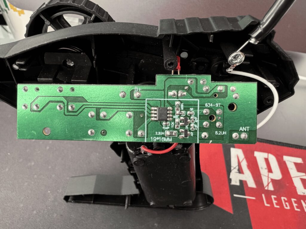
A microscope had to be used to see the information that was visible on the chip and the information is about a TXM TX-2 LX-40X .
The TXM TX-2 LX-40X chip is a radio frequency (RF) transmitter typically used in remote control toys and similar applications. Although it is not a very common component in detailed catalogs of large manufacturers, it appears to be part of low-cost, low-power RF data transmission systems.
Some typical characteristics of this type of chip are:
Power consumption: They are designed to be low power consumption, ideal for devices that rely on small batteries.
Operating frequency: They usually work in license-free frequency bands, such as 27 MHz, 40 MHz, or 433 MHz, which are common for remote control devices such as toy cars.
Modulation: These chips typically use amplitude modulation (AM) or frequency modulation (FM), allowing signals to be transmitted and received over a moderate range (a few meters to hundreds of meters in some cases).
Operating voltage: Most of these chips operate at low voltages, typically in the 3V to 5V range.
Transmission range: Depending on the antenna and environment, they typically have an effective range that can range from a few meters to several tens of meters under optimal conditions.
By the back of the card you will notice and verify the frequency information of this chip.
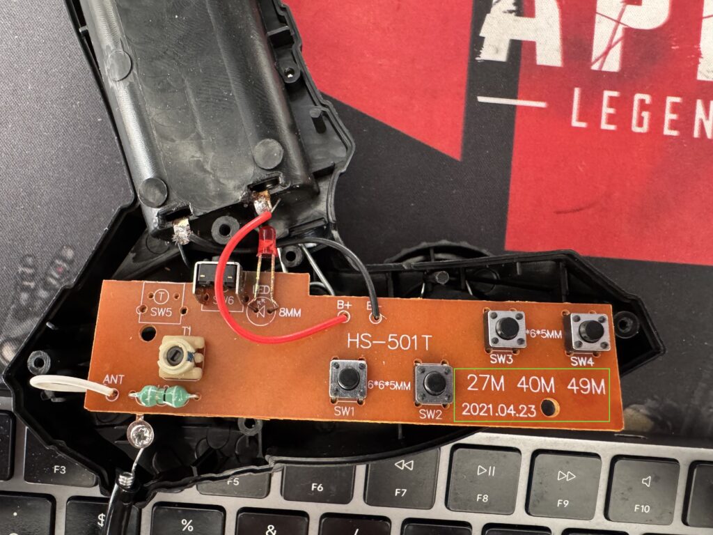
Frequency definition
Then according to the information printed on the PCB you could observe frequencies of 27MHZ, 40MHZ and 49MHZ, you will use hackrf-spectrum-analyzer to see if the signals are present in this radio control.
Just set the program to frequencies in the range of 1 MHz to 50 MHz and start pressing the control buttons.
The signal is fully visible at the 27MHz frequency.
Replay Attack
Let’s start our hack with the easiest exercise: the replay attack. But what is a replay attack and how does it work?
A replay attack, also known as a replay assault, is a type of cyber attack that targets wireless communication systems and involves capturing and then retransmitting valid data packets to impersonate a legitimate user or device.
Here’s how a radio wave replay attack typically works:
- Data capture: The attacker uses specialized hardware or software to intercept and capture the radio frequency signals transmitted between two legitimate parties (for example, between a wireless sensor and a control system).
- Data replay: After capturing the data packets, the attacker stores them for later use. The captured packets contain essential information such as authentication credentials, control commands, or any other sensitive data that can be used for malicious purposes.
- Replay attack: Later, the attacker resends the captured data packets back to the communication channel. Since the data packets are valid and were previously captured in a legitimate communication session, the receiving system can perceive them as coming from a genuine source and act accordingly.
The impact of a successful radio wave replay attack can vary depending on the system targeted. In some cases, it could lead to unauthorized access to a secure network, manipulation of control commands, impersonation of legitimate users, or the exfiltration of sensitive information.
Speaking of controlling the toy car, the impact is high… as you could take control of the vehicle and jam its signal if you so wish.
HackRF CA Transfer
The first replay attack approach on our list is to use the default HackRF apps: hackrf_transfer.
Before we actually pick up the signal and transmit it back, let’s figure out which keys in the app are crucial for our attack:
- r – saves data to file (we’ll use this during the capture phase)
- t – transmits data from file (we’ll use this during the attack on its own)
- f – frequency in Hz
- s – sampling rate in Hz
- x – TX VGA (IF) gain (how powerful the transmitter is)
Okay, let’s put it all together and write the receive command:
The following list of commands captures each of the functionalities that the car control has which are:
- Motor forward
- Motor reverse
- Steering Right
- Left direction
- Smoke (has a button to simulate smoke through a humidifier)
hackrf_transfer -f 27e6 -s 2000000 -r rigth_direction_car
hackrf_transfer -f 27e6 -s 2000000 -r left_direction_car
hackrf_transfer -f 27e6 -s 2000000 -r reverse_car
hackrf_transfer -f 27e6 -s 2000000 -r run_car
hackrf_transfer -f 27e6 -s 2000000 -r smoke_car
The arguments are explained below.
-f 27e6: the working frequency, in our case it is 27.0 MHZ-s 2000000: the sampling frequency, in our case it is 2 MHz-r/-t capture_name: write/read the sampling file-x 45: transmission power, in our case 45dB
If you have done everything correctly, you should receive and save the signal and then transmit it back: the control should work.
Obtaining the payload
Okay, the replay attack is a great feature if you want to save time and the signal is permanent and does not change (rotating code). But knowing what is behind it, how it works and, based on your knowledge, synthesizing the exact same signal with the payload is the best. Let’s disassemble the remote control signal and synthesize it again.
Universal Radio Hacker
We start with our old friend, URH. We capture the signal, save it and keep it open on the analysis page.

So the window is split into 3 parts:
- The left one with some settings (leave it as it is so far)
- The top right one with the analog signal.
- The bottom right one with the code demodulator.
As we can see, the signal is pretty clean and accurate, and even the demodulator shows the same values every time, which is quite rare.
First of all, what we can do, although it is not necessary in this particular case, is to remove the blank signal. You can do that by selecting the payload and “Trim Selection” or by selecting the blank and “Remove Selection”. We prefer the first approach because it requires less effort.
After that, we get only the payload without any blanks.

Now, let’s zoom in on the picture. What can you tell us about the signal? First, it is repeatable, meaning it sends the same payload (not the rolling code) every time. In that case, we can only consider one set of payloads instead of all of them.
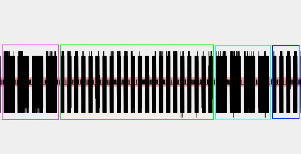
We can see that this signal has 4 moments, so to speak, and that we can be talking about a binary FSK signal where there are two frequencies alternating throughout the signal, representing the bits 0 and 1.
In FSK, the bits ‘0’ and ‘1’ are represented by two different frequencies:
- A bit
0is represented by a low carrier frequency. - A bit
1is represented by a high carrier frequency.
So if we decided to represent the signal in binary values for this image we would have the following.


Signal synthesis
So what have we done? We defined the frequency – ~27 (27 MHz), captured the signal, analyzed it and got the payload. The next logical step is to generate, i.e. using the generalized definition, synthesize the signal with the payload so that the controller can send the smoke signal without touching the button. That being said, let’s do it.
As the main tool we will use GNU Radio Companion for which we will launch the application and create a new project.
Let’s start with 2 variables: the sampling rate as 2 MHz and the frequency as 27 MHz.
Now, find and add the new block called “Vector Source”. The “Vector Source” block is a fundamental source block used to generate a sequence of complex numbers, forming a vector, which serves as an input signal for our signal processing flowchart. This block allows us to manually define the values of the complex vector, which can represent a variety of signals or data.
The vector is placed in parentheses, divided by commas in the format (0, 0, 0). In our case, using the simple format of 01110111011101110101010101010101010101010101010101010101010101011101110111010101010, the vector will be as follows:
(0,1,1,1,0,1,1,1,0,1,1,1,0,1,1,1,0,1,0,1,0,1,0,1,0,1,0,1,0,1,0,1,0,1,0,1,0,1,0,1,0,1,0,1,0,1,0,1,0,1,0,1,0,1,0,1,0,1,0,1,0,1,1,1,0,1,1,1,0,1,1,1,0,1,1,1,0,1,0,1,0,1,0,1,0)
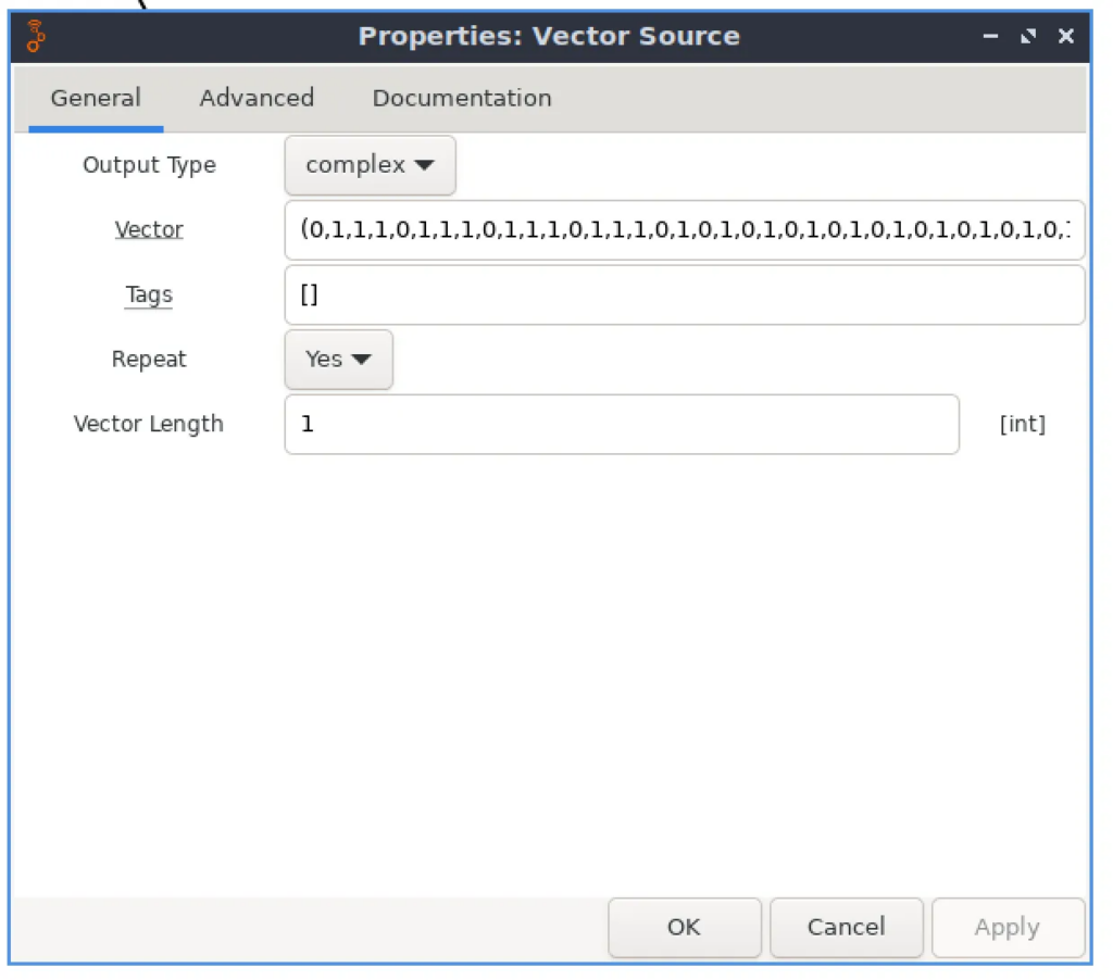
Next, we need to connect it with another block called “Repeat” (number of times the input is repeated, acting as an interpolation factor). Why do we need it? Basically, every payload, every spike, and even every pause has a duration. So, to generate the correct payload, we need to know the duration of the signal and implement it in our schematic.
For this, we can use URH and correctly select the shortest spike and observe the result.
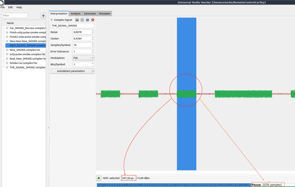
In our case there are a number of 1076 samples, put this in our Repeat field

Just to check that everything works fine, let’s add “QT GUI Time Sink” and run the script.
So the final scheme is as follows.
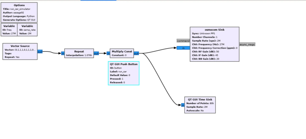
After analyzing the other signals this is the general formula for all buttons.
RUN     => "0111"*4 + "01" * 10 + "0111" * 4 + "01"* 4
REVERSE => "0111"*4 + "01" * 40 + "0111" * 4 + "01"* 4
SMOKE   => "0111"*4 + "01" * 22 + "0111" * 4 + "01"* 4
RIGHT   => "0111"*4 + "01" * 58 + "0111" * 4 + "01"* 4
LEFT    => "0111"*4 + "01" * 64 + "0111" * 4 + "01"* 4
RUN => (0,1,1,1,0,1,1,1,0,1,1,1,0,1,1,1,0,1,0,1,0,1,0,1,0,1,0,1,0,1,0,1,0,1,0,1,0,1,1,1,0,1,1,1,0,1,1,1,0,1,1,1,0,1,0,1,0,1,0,1,0)
SMOKE => (0,1,1,1,0,1,1,1,0,1,1,1,0,1,1,1,0,1,0,1,0,1,0,1,0,1,0,1,0,1,0,1,0,1,0,1,0,1,0,1,0,1,0,1,0,1,0,1,0,1,0,1,0,1,0,1,0,1,0,1,0,1,1,1,0,1,1,1,0,1,1,1,0,1,1,1,0,1,0,1,0,1,0,1,0)
REVERSE => (0,1,1,1,0,1,1,1,0,1,1,1,0,1,1,1,0,1,0,1,0,1,0,1,0,1,0,1,0,1,0,1,0,1,0,1,0,1,0,1,0,1,0,1,0,1,0,1,0,1,0,1,0,1,0,1,0,1,0,1,0,1,0,1,0,1,0,1,0,1,0,1,0,1,0,1,0,1,0,1,0,1,0,1,0,1,0,1,0,1,0,1,0,1,0,1,0,1,1,1,0,1,1,1,0,1,1,1,0,1,1,1,0,1,0,1,0,1,0,1,0)
RIGTH => (0,1,1,1,0,1,1,1,0,1,1,1,0,1,1,1,0,1,0,1,0,1,0,1,0,1,0,1,0,1,0,1,0,1,0,1,0,1,0,1,0,1,0,1,0,1,0,1,0,1,0,1,0,1,0,1,0,1,0,1,0,1,0,1,0,1,0,1,0,1,0,1,0,1,0,1,0,1,0,1,0,1,0,1,0,1,0,1,0,1,0,1,0,1,0,1,0,1,0,1,0,1,0,1,0,1,0,1,0,1,0,1,0,1,0,1,0,1,0,1,0,1,0,1,0,1,0,1,0,1,0,1,0,1,1,1,0,1,1,1,0,1,1,1,0,1,1,1,0,1,0,1,0,1,0,1,0)
LEFT =>(0,1,1,1,0,1,1,1,0,1,1,1,0,1,1,1,0,1,0,1,0,1,0,1,0,1,0,1,0,1,0,1,0,1,0,1,0,1,0,1,0,1,0,1,0,1,0,1,0,1,0,1,0,1,0,1,0,1,0,1,0,1,0,1,0,1,0,1,0,1,0,1,0,1,0,1,0,1,0,1,0,1,0,1,0,1,0,1,0,1,0,1,0,1,0,1,0,1,0,1,0,1,0,1,0,1,0,1,0,1,0,1,0,1,0,1,0,1,0,1,0,1,0,1,0,1,0,1,0,1,0,1,0,1,0,1,0,1,0,1,0,1,0,1,0,1,1,1,0,1,1,1,0,1,1,1,0,1,1,1,0,1,0,1,0,1,0,1,0)
Finally the complete graphic in GNU Radio with the button controls is the following:
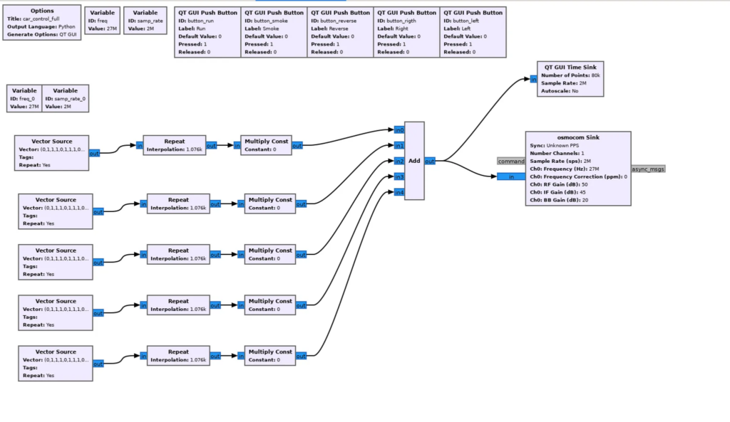
Finally, by reverse engineering a remote control that operates at 27 MHz, the signal transmitted by each button of the control was examined, identifying its structure and essential parameters (such as modulation, pulse duration, and specific patterns of each command). This analysis allowed the signal of each button to be recreated or “synthesized.”
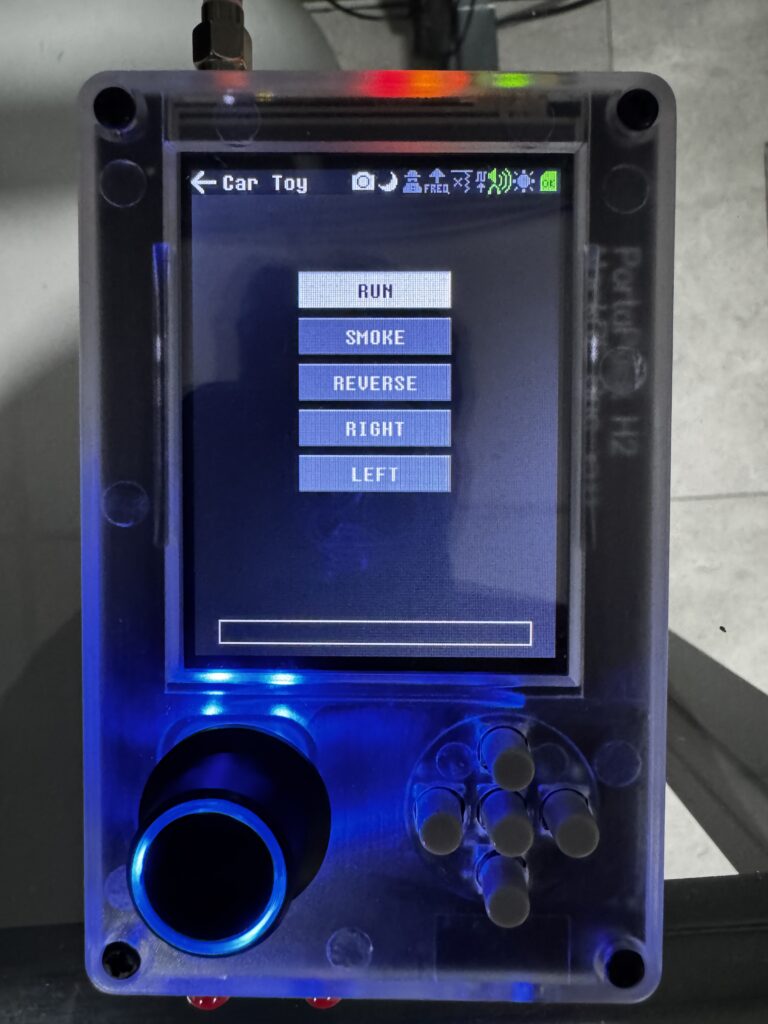
Using GNU Radio, a software specialized in signal processing, waves were generated that emulate the pulses and modulation of the original signals of the remote control. This allowed the operation of the control to be simulated, replicating its commands accurately without the need for the physical device, thus achieving complete control through the synthesized signal.




Leave a Comment