
In this research we performed a physical control attack on a drone by injecting PWM signals directly to the receiver, replicating the commands that would normally be sent by the remote control.
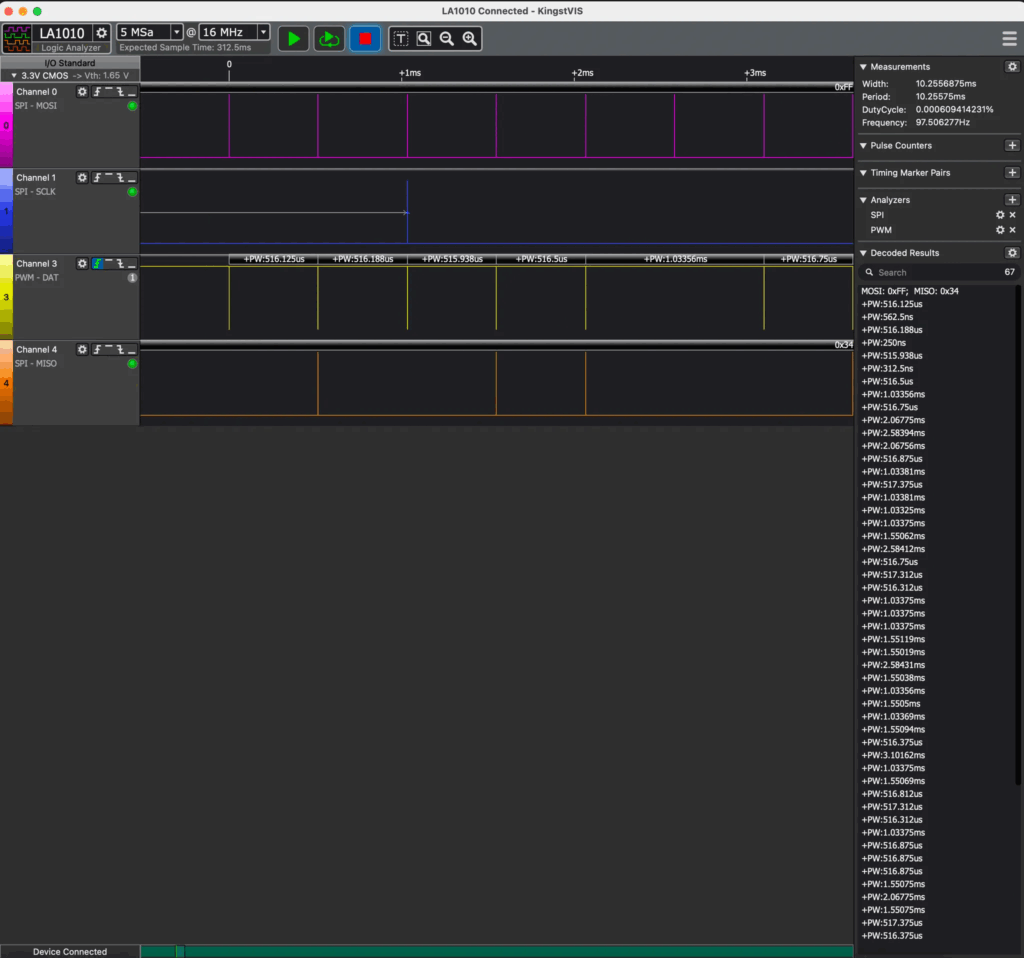
First, we captured the original PWM signals using a logic analyzer while pressing specific buttons on the control (such as lowering camera, turning on propellers, etc.).
Then, we analyzed the pulse sequences (duration, frequency, pattern) and reconstructed them from a Raspberry Pi Pico, which was programmed to exactly reproduce those pulse trains through one of its GPIO pins.
This approach demonstrated that it is possible to emulate valid remote control commands without sending RF data or interacting with the network layer, attacking directly at the physical level.
The experiment confirms that many drones lack authentication or command validation at the signal level, leaving them exposed to physical PWM injections, even without access to the original control or its wireless protocol.
Recognition
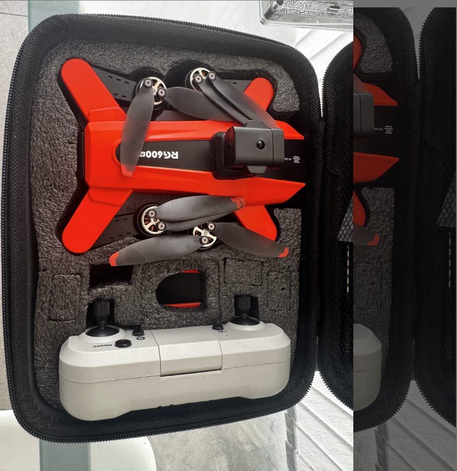
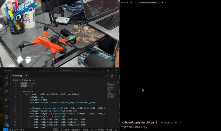
One of the challenges we decided to take on was the idea of tackling something we didn’t know, no context, chip brands or datasheet, so we approached this process completely from scratch, let’s see a little bit, the victim Drone RG600Pro
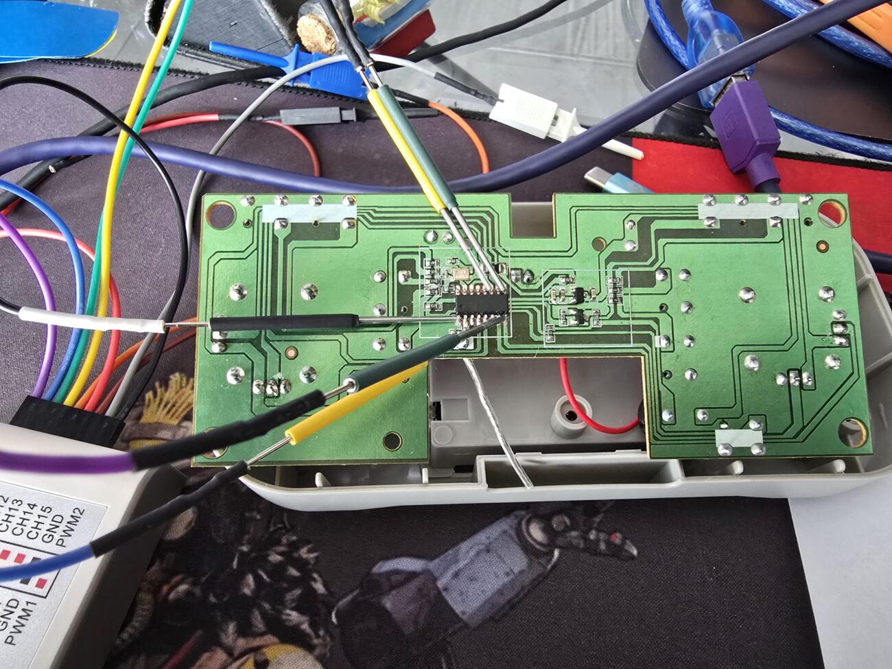
the inside of its control is as follows.

Since I had no idea what this chip was, our first steps were to measure voltages and perform a recognition with the logic analyzer of what we would be seeing on each of the pins of the main control chip.
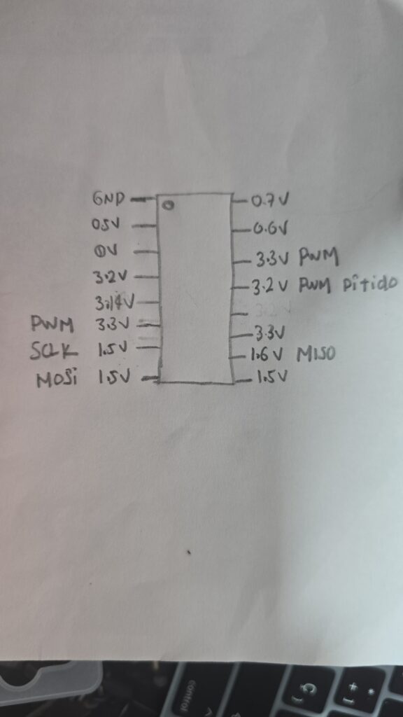
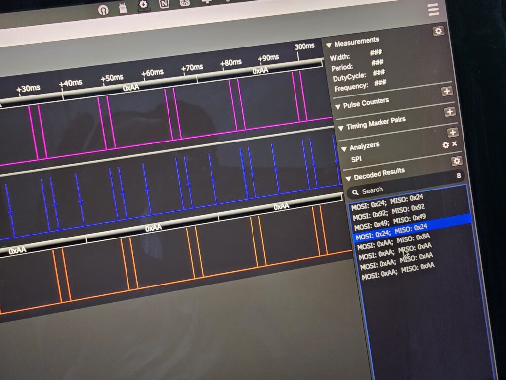
Several of the pins were identified through the logic analyzer, we had two types of protocols and signals, SPI and PWM.
The identification of these signals was performed by pressing each of the buttons on the drone control, and capturing the signals in the logic analyzer, once this objective was achieved we were able to successfully decode the SPI and PWM signals.
After several captures, we decided to perform a functionality injection through the PWM signal that the controller sent to the drone.
The idea was to faithfully emulate the PWM signal from the original remote control, allowing the drone to respond to the command as if it had been sent by the real control. This injection technique is effective because the drone’s receiver does not validate authenticity, it only interprets pulses.
PWM signal injection
To achieve this process we only had to use a pico raspberri that has PWM outputs on its pin configurations, and emulate one of the signals that we captured through the logic analyzer.
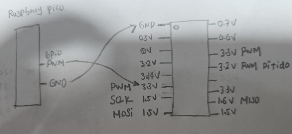
So we connected the pins from the rapsberry pico to the drone control chip and were able to faithfully replicate one of the functionalities.
from machine import Pin
import time

# Output pin
pwm_pin = Pin(19, Pin.OUT)

# Pulse train captured
pulse_durations_us = [
    517, 1551, 517, 1034, 1551, 1550, 1034, 516, 517, 517,
    1034, 1034, 516, 1034, 2585, 1034, 2585, 1034, 3619, 516,
    1034, 517, 516, 2585, 1034, 1034, 517, 1550, 517, 516,
    517, 2067, 1034, 1034, 1034, 516, 3102, 517, 517, 1551,
    1551, 3102, 516, 1034, 1551, 517, 1551, 1551, 517, 1034,
    518, 1551, 517, 518, 516, 517, 2068, 1552, 1034, 2068,
    517, 516, 1034, 517, 1034, 1035
]

def send_pulses():
    for _ in range(6):  # Repeat only 3 times
        for duration in pulse_durations_us:
            pwm_pin.high()
            time.sleep_us(duration)
            pwm_pin.low()
            time.sleep_us(200)  # Between pulses
        time.sleep_ms(10)  # Short break between trains

    # Final resting state
    pwm_pin.high()
    time.sleep_ms(100)

# Execute
send_pulses()
Aspects that we had to consider in the Raspberry Pi Pico for PWM injection
- Suitable output GPIO pin
- We selected a pin (GPIO19 in your case) that supports digital output with good timing stability.
- This pin was configured as Pin.OUT to generate the PWM signal manually (bit banging).
- Timing accuracy
- The signal captured from the drone control was very sensitive to microsecond pulse widths.
- We used time.sleep_us() to ensure accurate times in microseconds.
- A small spacing between pulses (sleep_us(200)) and between trains (sleep_ms(10)) was also respected.
- Signal frequency
- Although a “continuous” PWM signal was not generated, the effective pulse frequency was crucial.
- The pulse_durations_us values reflect an accurately captured pulse train that was to be replicated without distortion or jitter.
- Format of the pulse train
- The signal was composed of a precise sequence of variable pulse widths (between 500 µs and >3 ms).
- It is essential to reproduce the entire complete pattern, as the drone interprets that as a valid command (such as “turn on” or “activate camera”).
- Pulse train repetition
- Some devices require the pulse train to be repeated several times to be recognized.
- Therefore the loop repeats the train 6 times (for _ in range(6)).
- Appropriate logic level
- The Raspberry Pi Pico operates at 3.3V, and is compatible with many PWM devices, but:
- If the drone expected 5V, a level shifter would be needed.
- In this case, apparently 3.3V was enough to activate the drone’s receiver pin.
- The Raspberry Pi Pico operates at 3.3V, and is compatible with many PWM devices, but:
- Idle condition of the pin
- After finishing the send, the pin was left in the high state (pwm_pin.high()) for 100ms.
- This simulates the behavior of the real controller, avoiding false commands after injection.
Conclusion
PWM pulse injection from a Raspberry Pi Pico proved to be an effective technique to emulate control commands on a drone, accurately replicating the pulse train of the original control. This test confirms that, with proper timing and without the need for wireless communication, it is possible to manipulate physical devices at a low level, opening the way to new forms of analysis and attack in embedded environments.


Leave a Comment